A hydropower unit cannot complete its automatic operating sequence without dependable information about rotational speed and frequency. The control system needs to know whether the unit is stationary, accelerating, approaching synchronous speed, operating normally or decelerating after shutdown.
However, a speed signal device should not be viewed as a simple display instrument. Its measured values, status signals and alarm outputs may be used by the governor, unit automation system and protection logic. For this reason, the signal sources, thresholds, interfaces and failure monitoring must be considered as part of the complete unit control design.
Where Do Hydropower Speed Signals Come From?
Speed and frequency information can be obtained from more than one source. In the RES-2000 configuration, the available frequency inputs include one signal from the generator terminal voltage transformer and two signals from the speed-measuring gear disc.
The voltage-transformer input provides an electrical-frequency signal when suitable generator terminal voltage is available. A gear-disc pickup produces pulses related to shaft rotation and can provide a mechanical speed reference. How these inputs are assigned, compared and used depends on the unit design and its automatic control logic.
Using multiple inputs does not by itself guarantee reliable operation. The pickup arrangement, gear-tooth information, wiring, shielding, input frequency range and control logic must all be correctly engineered and verified during commissioning.
How Speed Information Is Used
Different stages of unit operation require different speed-related information. Depending on the project design, speed signals may support:
- Confirmation of zero speed or standstill
- Start-up and shutdown sequence transitions
- Monitoring of unit acceleration and deceleration
- Indication of speed as a percentage value
- Frequency and speed-limit alarms
- Status information supplied to the governor or plant monitoring system
- Event analysis when an abnormal condition occurs
The speed signal device provides measurements, indications, records and output signals. The governor, automation system and protection equipment then use those signals according to the plant’s approved control logic.
A speed monitoring device therefore does not replace the turbine governor or independent mechanical and hydraulic protection devices.
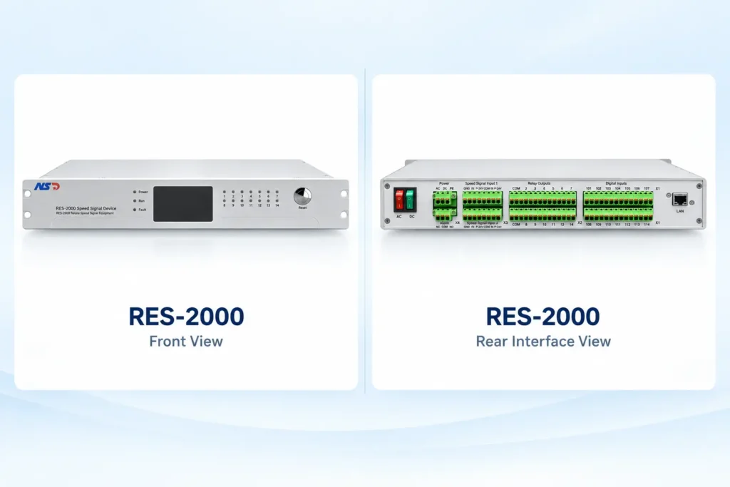
What the RES-2000 Monitors
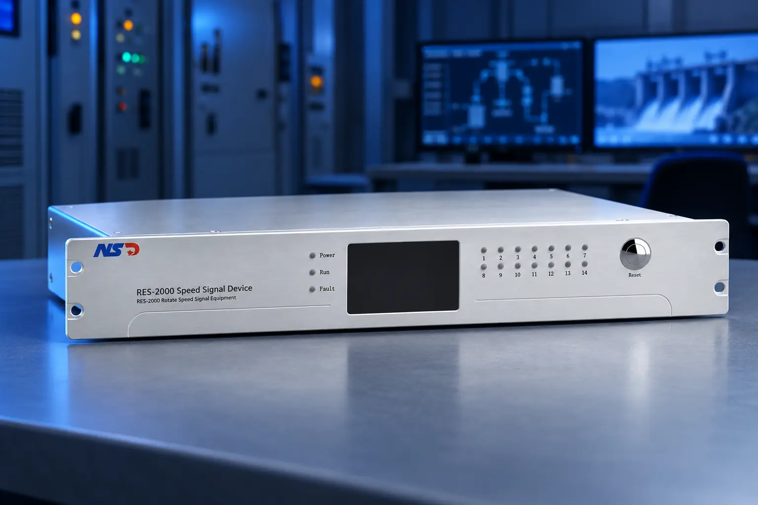
NSD Electric developed the RES-2000 Speed Signal Device for the measurement and monitoring of hydro-generator speed and frequency. It uses an industrial-grade microcontroller as its main control unit and is designed to support single-unit automation and protection systems.
The device accepts one PT frequency input from the generator terminal voltage transformer and two gear-disc frequency inputs. It also provides one analogue voltage or current output for remote monitoring.
Its LCD touch screen can display output frequency, individual input frequencies, speed percentage, channel fault codes, contact action information, operating records and the maximum recorded speed. This allows operators and commissioning personnel to check both the measured value and the status of the associated channels.
For post-event review, the RES-2000 records events with the corresponding fault time and speed. Frequency values and digital status information can be transmitted through RS485, while a rear network port supports connection to a computer for parameter configuration.
The device also provides zero-speed, configurable limit, self-test and frequency-loop fault alarms. Seventeen LED indicators show power, device, channel and alarm status.
Published Technical Data
The following information is taken from the official RES-2000 product page:
| Item | Published specification |
|---|---|
| Operating temperature | −25°C to +65°C |
| Relative humidity | ≤95%, non-condensing |
| Power supply | AC/DC 220 V, dual input; 50/60 Hz for AC supply |
| Power consumption | ≤30 W |
| Frequency inputs | 1 PT frequency input and 2 gear-disc frequency inputs |
| Analogue output | 1 voltage or current output |
| Communication | RS485 for frequency and digital status; rear network port for configuration |
| Installation | Panel cut-out or standard 19-inch rack mounting |
| Testing functions | Built-in fixed-value and hardware self-test functions |
These specifications describe the device itself. They should not be treated as confirmation that it can be installed in every plant without additional engineering. Signal compatibility, output requirements, cabinet conditions and control-system interfaces still need to be checked for each project.
What Should Be Checked Before Selection or Retrofit?
1. Existing Signal Sources
Confirm whether the unit uses a generator-terminal PT signal, gear-disc pickups or both. The gear geometry, pickup type, wiring method and actual signal condition should be documented.
2. Required Speed Thresholds
List every threshold required by the unit automation and protection logic. The corresponding contacts, reset conditions, delay settings and destination systems should be clearly defined.
Values must be determined from the approved unit design; they should not be copied from another power station.
3. Output and Communication Interfaces
Confirm which hardwired contacts, analogue signals and communication data are required by the governor, unit control system, plant monitoring system and protection equipment.
4. Power Supply and Installation Conditions
Check the available control power, cabinet opening, rack arrangement, ambient temperature, humidity and grounding conditions against the device requirements.
5. Test and Commissioning Plan
Commissioning should verify the individual input channels, displayed frequency, speed-percentage calculation, alarm thresholds, output contacts, communication data, event records and self-test functions.
The complete signal chain should then be tested together with the receiving systems.
Reliable Measurement Requires System-Level Coordination
The value of a speed signal device is determined not only by its hardware but also by how it is integrated into the unit control system. Correct signal acquisition, documented thresholds, compatible interfaces and coordinated testing are all necessary for dependable operation.
For retrofit projects, this system-level review is especially important because the new device may need to work with existing pickups, wiring, governors, PLCs and protection circuits. Verifying these interfaces before installation helps establish a clear and testable retrofit scope.
NSD Electric provides the RES-2000 Speed Signal Device together with turbine governor systems, automation equipment, retrofit components, engineering configuration and technical support for hydropower projects.