| Specifications | Technical Data |
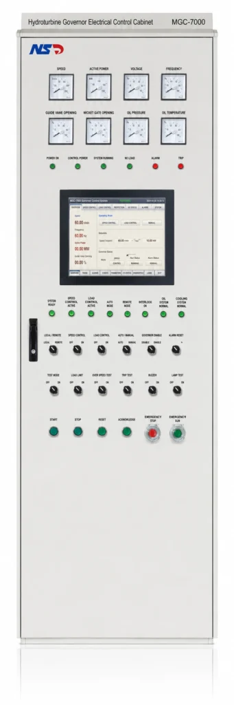
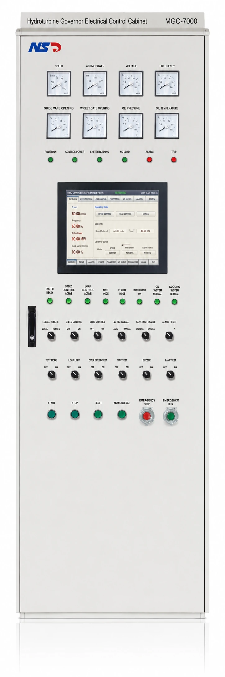
| Cabinet Features | |
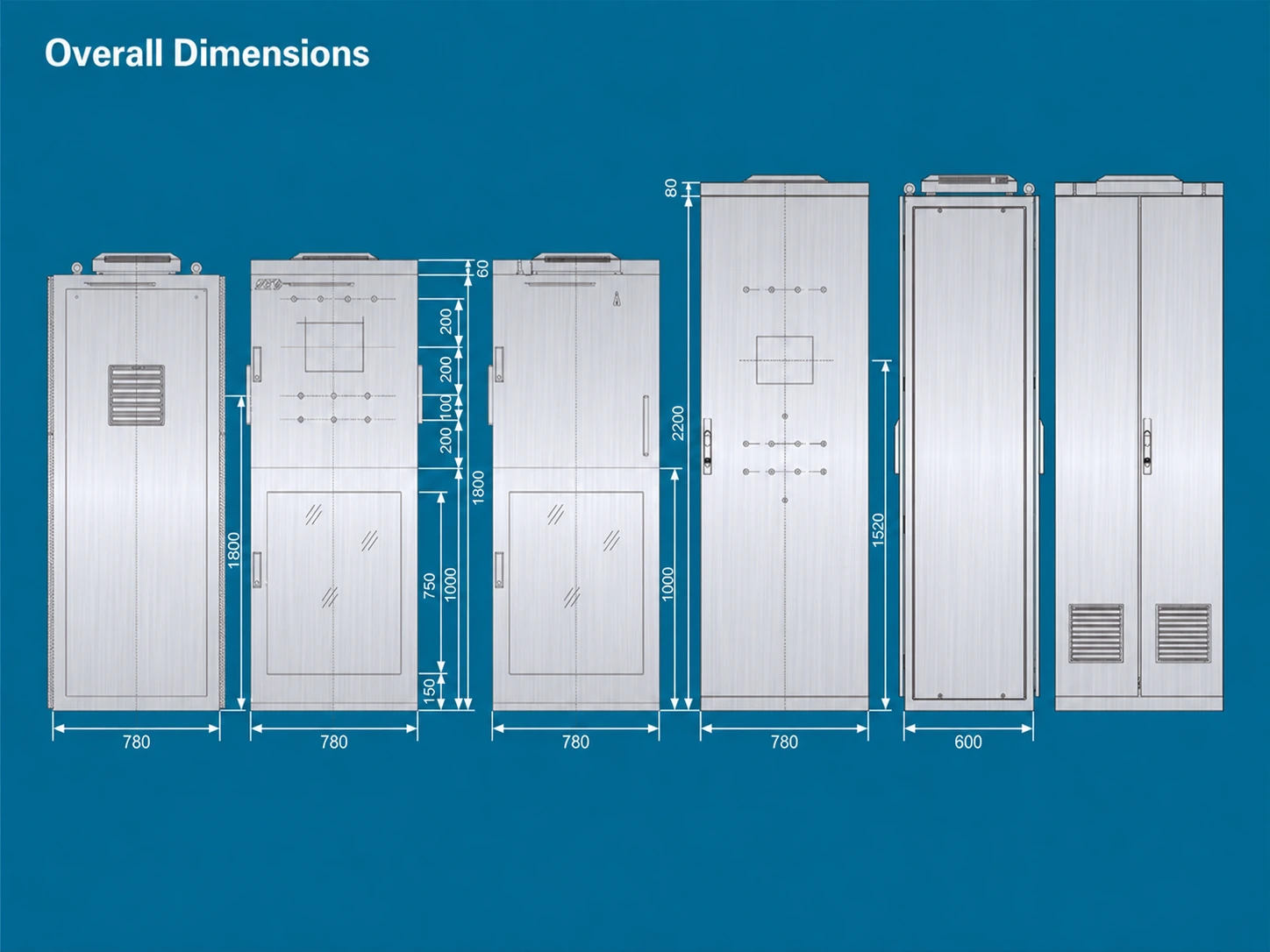
| Integrated electrical-mechanical cabinet dimensions | 800 × 800 × 1860 mm (L × W × H), customizable |
| Separate electrical cabinet dimensions | 600 × 800 × 2260 mm or 800 × 800 × 2260 mm (L × W × H) |
| Cabinet weight | 300 kg |
| Standard AC operating voltage | AC 220 V ±15% |
| Standard DC operating voltage | DC 110 V ±10%, DC 220 V ±15% |
| Load capacity | 2200 W (VA) |
| Dielectric withstand test | 1.5 kV, 1 min |
| Protection degree | IP65 |
| Operating temperature range | -40 to 65°C |
| Insulation resistance | >10 MΩ |
| Leakage current | <1 mA |
| Control Signal Output | |
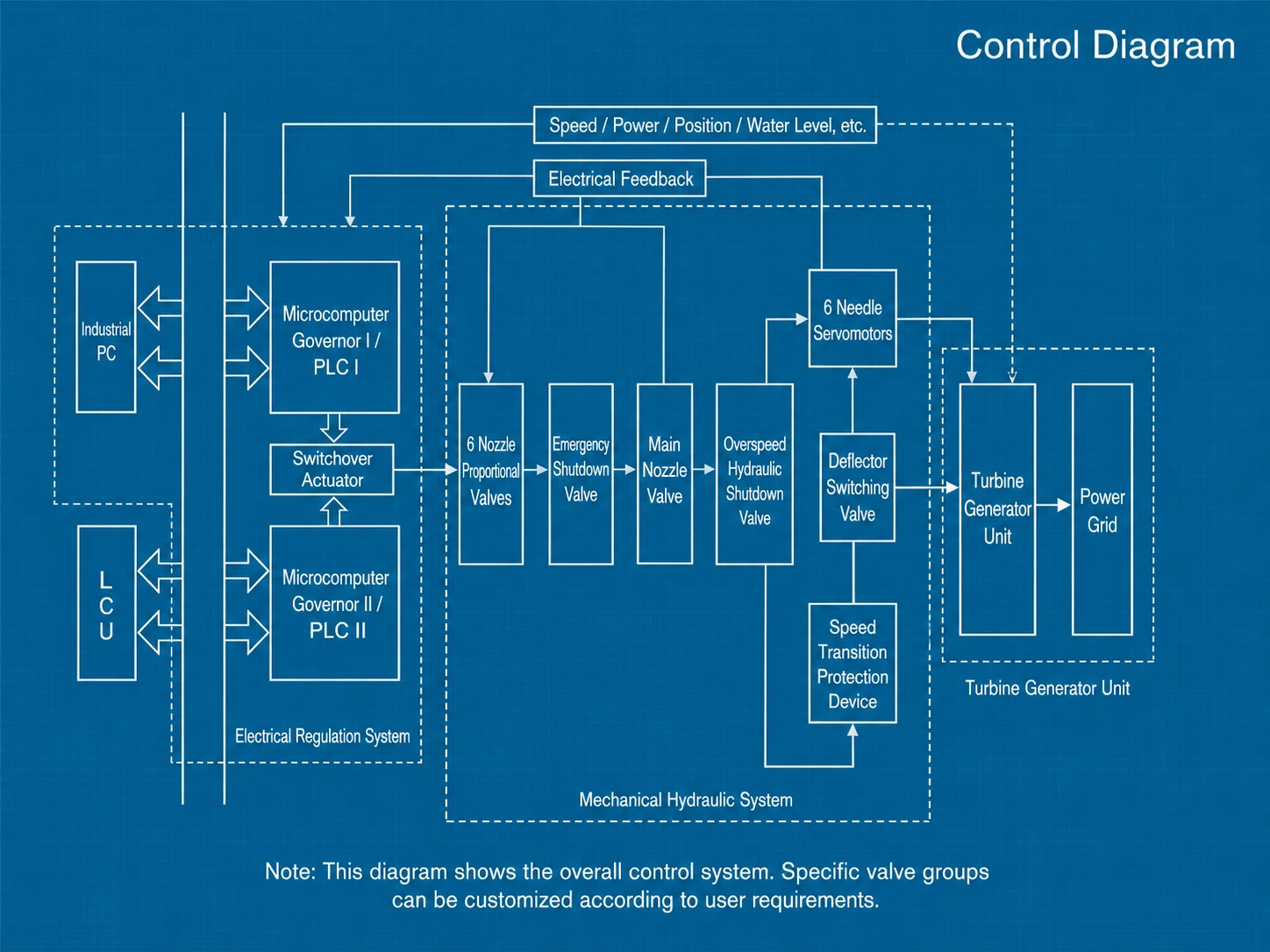
| Servo motor | Servo motor driver output |
| Proportional valve | Analog current channel, 4–20 mA |
| Input Characteristics | |
| Digital input | DC 24 V, LED indicator, fully isolated |
| Analog input | Voltage 0–10 V, current 4–20 mA, LED indicator, fully isolated |
| Output Characteristics | |
| Digital output | DC 24 V, LED indicator, fully isolated |
| Analog output | Voltage 0–10 V, current 4–20 mA, LED indicator, fully isolated |
| Frequency Measurement Specifications | |
| Measurement method | Frequency measured by controller body |
| Grid frequency | AC 30–150 V, 90–110% rated frequency |
| Unit frequency | AC 0.3–150 V, 7.8–110 Hz |
| Gear-disc speed measurement | Non-contact proximity switch, DC 24 V supply, 1–110 Hz |
| Frequency measurement resolution | 0.001 Hz |
| Frequency measurement channels | Residual unit voltage frequency, system frequency, unit gear-disc speed |