Switching off an excitation power supply does not make a generator’s magnetic field disappear immediately. The rotor field winding stores magnetic energy, and that energy must be released as the field current decreases.
This is why de-excitation is an important part of synchronous generator operation. Understanding the process explains what happens after an excitation shutdown command—and why the discharge circuit matters.
What Is De-Excitation?
During operation, excitation current establishes the rotor magnetic field. De-excitation reduces that current so that the field weakens.
The field winding has inductance, which opposes a rapid change in current. Disconnecting the excitation source therefore does not instantly reduce field current to zero. Current continues to decay through the available electrical path as stored magnetic energy is released. ABB’s generator protection guidance describes this process in a field-discharge arrangement, where a discharge resistor absorbs energy from the winding.
De-excitation concerns this electrical process. It does not mean that the rotor has stopped turning, nor does it replace the mechanical shutdown sequence.
Why Simply Opening the Field Circuit Is Not Enough
An inductive circuit behaves differently from a simple resistive load. Interrupting its current without an appropriate path can produce a high transient voltage.
Excitation systems must therefore manage both the decrease in field current and the voltage produced during that decrease. Depending on the design, switching devices and discharge components provide a path for the remaining current.
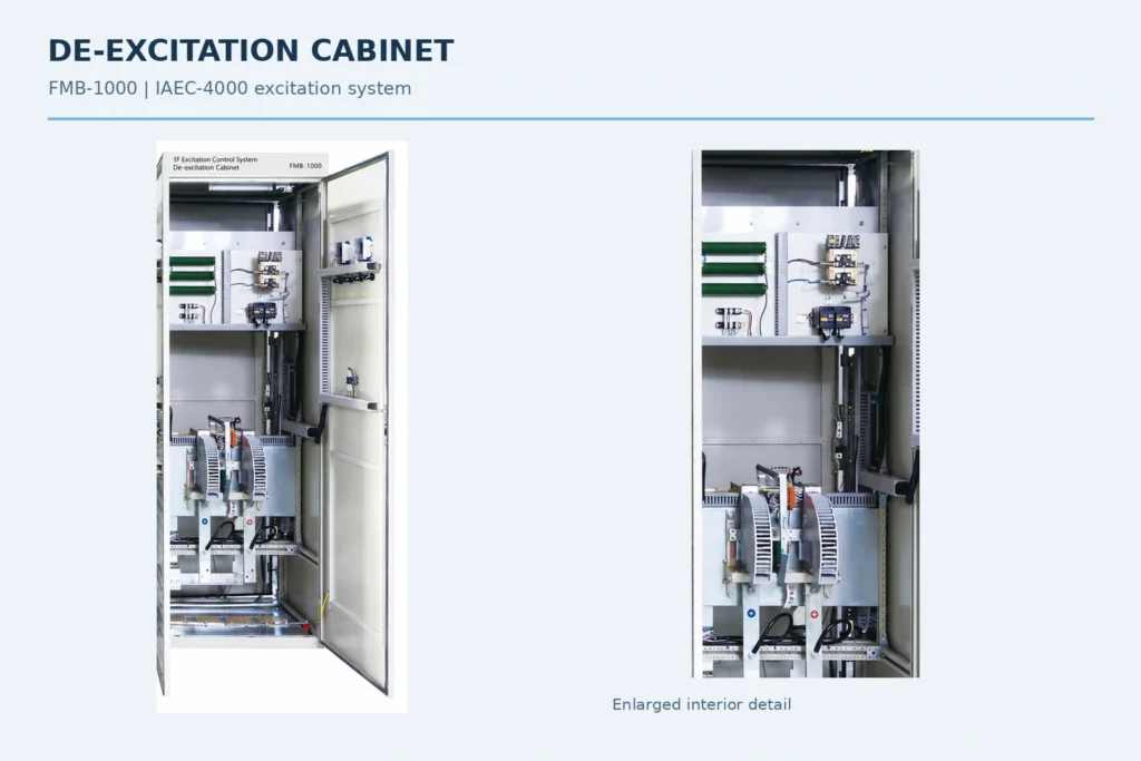
Manufacturer documentation describes de-excitation and crowbar modules that direct these currents into a field-discharge resistor arrangement, helping prevent excessive transient voltage and damaging arcs.
The purpose is more than disconnecting a source: the system must also handle the energy already stored in the field.
Where Does the Magnetic Energy Go?
In a resistor-based discharge arrangement, stored magnetic energy is converted into heat.
The resistor must accommodate the discharge duty, while the associated switching equipment and field insulation must withstand the resulting electrical stresses. Resistance, voltage and current decay are related, so faster discharge cannot be considered separately from voltage withstand and energy-handling requirements.
Some static excitation systems also use converter inversion to remove field energy. A suitable fully controlled bridge can apply a negative voltage while field current is still flowing in its original direction, accelerating the reduction of current. Negative field voltage in this process does not necessarily mean reversed field current.
Discharge resistors and inverter operation are established approaches, but their availability and use depend on the excitation system configuration.
Does Every Generator Use the Same Arrangement?
No. The excitation architecture affects how the main rotor field can be discharged.
In static excitation, the converter supplies the main field through brushes and slip rings. In a conventional brushless arrangement, an exciter and rotating rectifier supply the main rotor field. This changes access to the field circuit and its discharge behavior.
ABB’s published descriptions distinguish static systems with resistor or inverter discharge from conventional brushless systems with field discharge governed by the natural time constant.
A discharge arrangement suitable for one machine should therefore not be assumed suitable for another. The generator and excitation drawings are essential for understanding the actual circuit.
Normal Shutdown and Protective De-Excitation
A planned shutdown follows the plant’s defined operating sequence. Protective de-excitation responds to a condition requiring excitation removal as part of the protection scheme.
For technical discussions, it is useful to separate three questions:
- What initiates the de-excitation command?
- Which equipment disconnects or reduces the excitation supply?
- Which path handles the remaining field current and stored energy?
The answers should be considered alongside generator breaker operation and turbine shutdown. De-excitation is one coordinated action within the complete unit sequence; its timing and relationship to other actions are project-specific.
Regulation and De-Excitation Have Different Roles
The excitation regulator manages the operating control objective, such as generator terminal voltage or field current. De-excitation equipment handles the reduction of excitation and the associated energy discharge.
These functions work together, but they should be identified separately when reading system documentation.
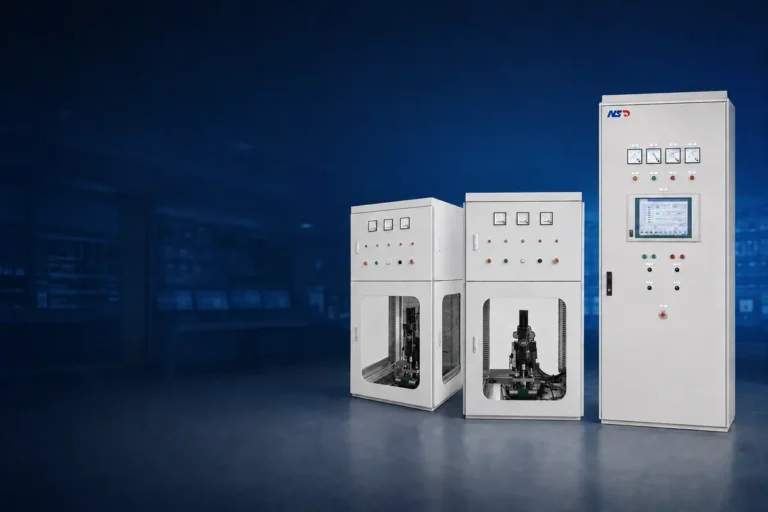
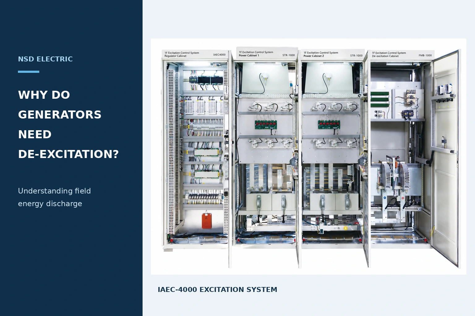
For an existing installation, a useful learning exercise is to trace the excitation supply, field winding, switching devices and discharge path on the approved schematic. This shows more than a cabinet photograph can: it reveals how the system manages current after the supply is removed.
Understanding de-excitation begins with a simple principle: magnetic energy does not disappear when a switch opens. A suitable excitation system provides a defined way for that energy to leave the field circuit.