Excitation control plays an essential role in the operation of a synchronous hydropower generator. By controlling the electrical energy supplied to the rotor field, the excitation system supports generator voltage regulation and reactive power control. Understanding its operating modes helps plant owners and engineers evaluate equipment specifications and define retrofit requirements.
Two terms frequently appear in excitation system documentation: Automatic Voltage Regulation, or AVR, and Manual Current Regulation, or MCR. The main distinction is the electrical quantity being regulated. AVR controls generator terminal voltage, while MCR controls excitation current.
How Automatic Voltage Regulation Works
In AVR mode, the regulator uses the measured generator terminal voltage as feedback and compares it with a voltage reference. It adjusts excitation to reduce the difference between the measured voltage and the reference.
The operator or plant control system may adjust that reference, but the regulator performs the ongoing corrective action. An adjustable setpoint therefore remains part of an automatic control loop.
AVR responds to voltage deviations by changing excitation within the limits and control functions configured for the installation. It does not mean that excitation current stays constant: current changes as the regulator works toward its voltage-control objective.
What Manual Current Regulation Means
In a field-current-regulated manual mode, the regulator maintains excitation current at a selected reference. Similar functionality is often called Field Current Regulation, or FCR, in other manufacturers’ documentation.
“Manual” describes how the operating objective is managed. The operator selects or adjusts the current reference, while the current regulator continues to perform closed-loop control.
This distinction matters because maintaining excitation current does not provide the same response as maintaining generator terminal voltage. If operating conditions change, the operator may need to adjust the current reference to achieve the required generator operating condition.
The regulated current must also be identified correctly. In a static excitation arrangement, this may be the main generator field current; in other arrangements, the controlled quantity may relate to the exciter field. Project documentation should identify the measurement point and current scaling explicitly.
AVR and MCR Compared
| Aspect | AVR | MCR |
|---|---|---|
| Primary control objective | Generator terminal voltage | Excitation current |
| Main feedback quantity | Measured generator voltage | Measured excitation current |
| Reference quantity | Voltage setpoint | Current setpoint |
| Regulator action | Changes excitation to correct voltage deviation | Changes control output to correct current deviation |
| Operator adjustment | Changes the voltage reference | Changes the excitation-current reference |
Both modes can involve automatic regulator action. The practical difference lies in the feedback quantity and control objective, rather than simply whether a person is involved. Manufacturer documentation illustrates this distinction by specifying the AVR reference in volts and the field-current reference in amperes.
Why Mode Transfer Deserves Attention
The presence of two operating modes raises another question: how does the system move between them?
Digital excitation systems may use tracking functions to align an inactive mode with the active operating condition. This helps reduce a sudden change in control output when a transfer occurs. However, tracking arrangements, transfer permissions and automatic transfer triggers vary between systems.
For example, manufacturer documentation describes configurable tracking and backup operation following certain sensing failures. These are examples of available engineering approaches, rather than functions that should be assumed for every excitation system.
For an equipment purchase or retrofit, the specification should establish which transfers are permitted, what initiates them, how the receiving reference is prepared and how the result will be verified.
Control Modes and Redundant Channels Are Different
AVR and MCR describe regulation modes. A dual-channel arrangement describes controller architecture.
These terms should be reviewed separately during technical discussions. A specification that lists two modes and two channels does not, by itself, explain the allocation of functions between controllers or the response to every possible failure.
Useful questions for the supplier include whether each channel supports the required modes, which measurements and power supplies are shared, and what conditions cause a transfer or shutdown. The answers should be recorded in the project’s control description and test plan.
What to Confirm in an Excitation Retrofit
Before selecting replacement equipment, plant owners should prepare generator and excitation-system data, existing drawings and the required operating philosophy.
The engineering review should then define:
- Measurement interfaces: Voltage sensing, current feedback, signal scaling and supervision.
- Operating references: Permitted setpoint ranges, adjustment methods and remote-control interfaces.
- Transfer behavior: Manual and automatic transfer conditions, tracking requirements and operator indications.
- Limits and protection: Which functions remain effective in each mode and how they coordinate with generator protection.
- Acceptance checks: The observations and criteria needed to demonstrate the agreed behavior.
This provides a clearer basis for comparison than a feature list alone. It also helps identify which existing interfaces can be retained and which need modification.
NSD Electric’s IAEC-4000 Excitation System
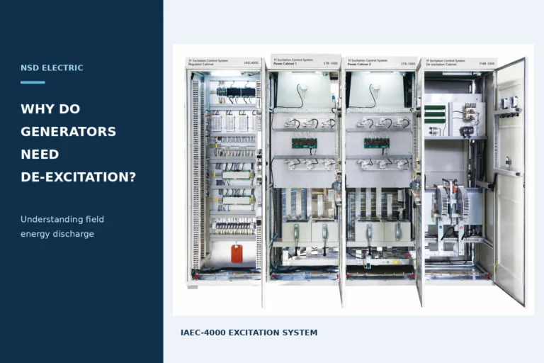
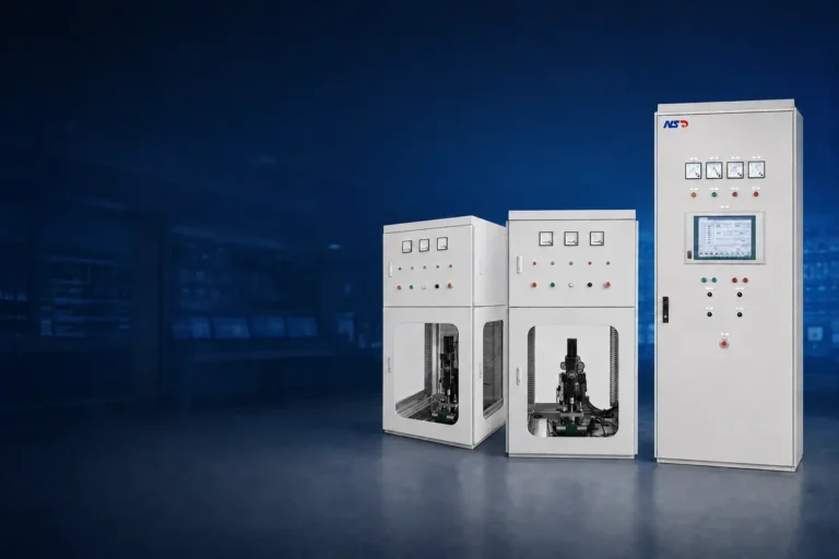
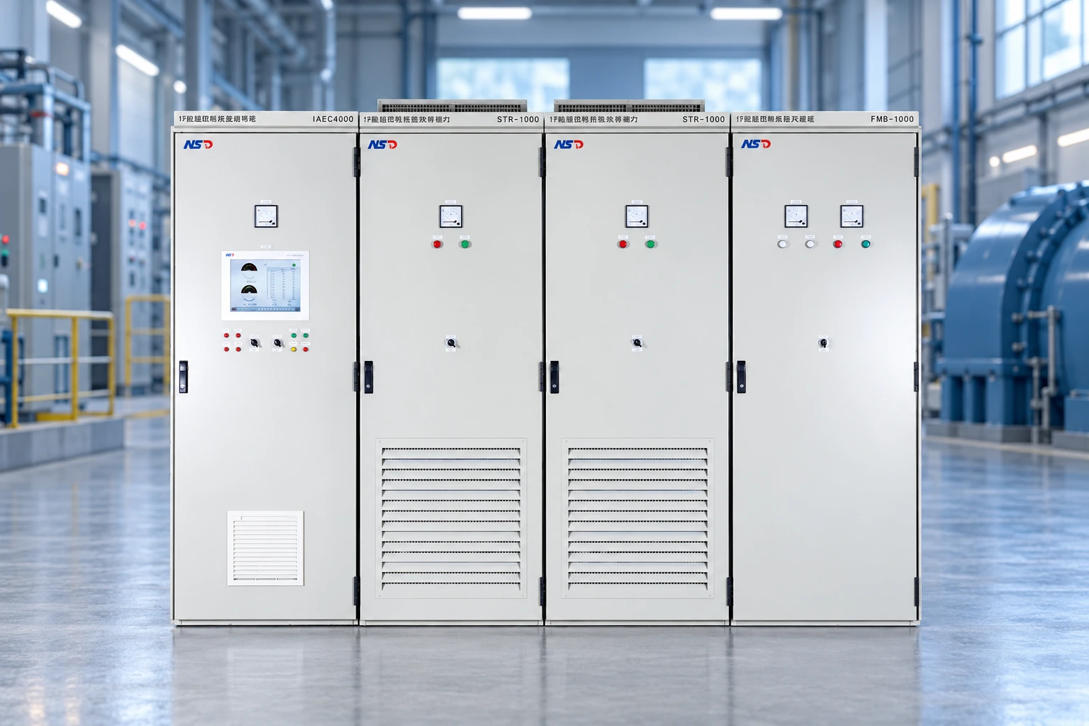
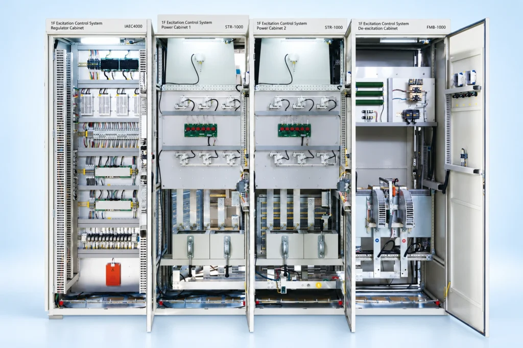
NSD Electric’s published IAEC-4000 information lists a dual-channel controller with AVR and MCR. The fully digital system is offered for 10 MW–600 MW generator units and uses separate regulation, power and de-excitation cabinets, with heat-pipe or forced-air cooling configurations.
For a specific installation, the detailed mode allocation, transfer logic, tracking functions and protection configuration should be confirmed against the project requirements.
Plant owners planning an excitation upgrade can begin by sharing their existing system drawings, generator field data and required control functions with NSD Electric. These inputs provide the basis for defining a suitable configuration and an agreed scope of verification.